
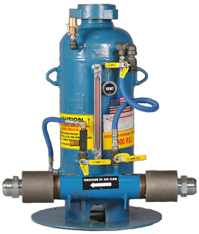
Description
Additional information
| Weight | 160 lbs |
|---|---|
| Dimensions | 44 × 42 × 36 in |
| Maximum Operating Pressure: |
| 7 and 12 gallon – 600 psi |
| 17 and 33 gallon – 1,000 psi |
| Sizes: |
| 7 gallon – 600 psi |
| 12 gallon – 600 psi |
| 17 gallon – 1,000 psi |
| 33 gallon – 1,000 psi |
| Manifold needs to be mounted at lubricator bracket level or lower. |
| Easy to remove cap |
| No moving parts |
| No pumps | No wiring | Venturi style |
| Infinite flow control with needle valve |
| Manifold can be removed from tank and mounted |
| remotely | Sight glass |
| Pressure vessel (A.S.M.E. Code Stamped) |
| 2″ or 3″ manifold |
| Fill while you drill | Fits any drill rig |
| Size | Base Diameter | Diameter at Manifold | Height | Weight |
|---|---|---|---|---|
| 7 gallon | 19″ | 25″ | 31″ | 160 lbs. |
| 12 gallon | 23 1/4″ | 29 1/4″ | 36 1/2″ | 210 lbs. |
| 17 gallon | 22 3/4″ | 27″ | 39″ | 375 lbs. |
| 33 gallon | 23 1/8″ | 29″ | 39 1/2″ | 675 lbs. |
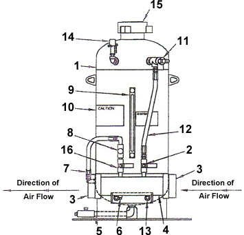
| Item | Quantity | Part Description |
|---|---|---|
| 1 | 1 | Tank Assembly |
| 2 | 1 | Inlet Valve (3/8″ Ball Valve) |
| 3 | 2 each | 2″ and 3″ Air Hose Spud |
| 4 | 1 each | 2″ and 3″ Air Manifold Assembly |
| 5 | 1 | Drain Pipe Assembly |
| 6 | 1 | 1/4″ Pipe Plug |
| 7 | 1 | Discharge Hose Assembly |
| 8 | 1 | 3/8″ Needle Valve Assembly |
| 9 | 1 | Sight Glass |
| 10 | 1 | Caution Sticker |
| 11 | 1 | 3/8″ Ball Valve |
| 12 | 1 | Intake Hose Assembly (20″ x 1/2″) |
| 13 | 2 | Bolt and Nut Assembly (3/8″ x 1 1/2″) |
| 14 | 1 | Safety Relief Valve Assembly |
| 15 | 1 | Fill Cap Coupling |
| 16 | 1 | Discharge Valve (3/8″ Ball Valve) |
| 1 | Connect air supply to inlet side of manifold, install whipcheck. |
| 2 | Connect outlet side of manifold to line going to hammer, install whipcheck. |
| 3 | Close vent valve #11. |
| 4 | Apply air pressure to manifold and open air intake valve #2. |
| 5 | Open oil line needle valve #8 four complete turns and lock in place. |
| 6 | Open discharge valve #16. |
| 7 | Operate hammer and check if bit is wet. A properly lubricated tool will be wet, but not dripping oil. |
| 8 | To control lubrication, adjust needle valve counter-clockwise to increase oil, clockwise to decrease. With correct adjustment, lock set screw and continue drilling. |
| 9 | To stop oiler, close air intake valve #2 and close discharge valve #16. |
| 1 | Close inlet valve #2. |
| 2 | Close discharge valve #16. |
| 3 | Open vent valve #11. |
| 4 | When air has bled out of tank, remove fill cap #15. |
| 5 | Fill lubricator tank with rock drill oil. |
| 6 | Replace fill cap #15. |
| 7 | Close vent valve #11. |
| 8 | Open inlet valve #2. |
| 9 | Open discharge valve #16. |
| Weight | 160 lbs |
|---|---|
| Dimensions | 44 × 42 × 36 in |
$99.00
$89.00 – $1,150.00Price range: $89.00 through $1,150.00